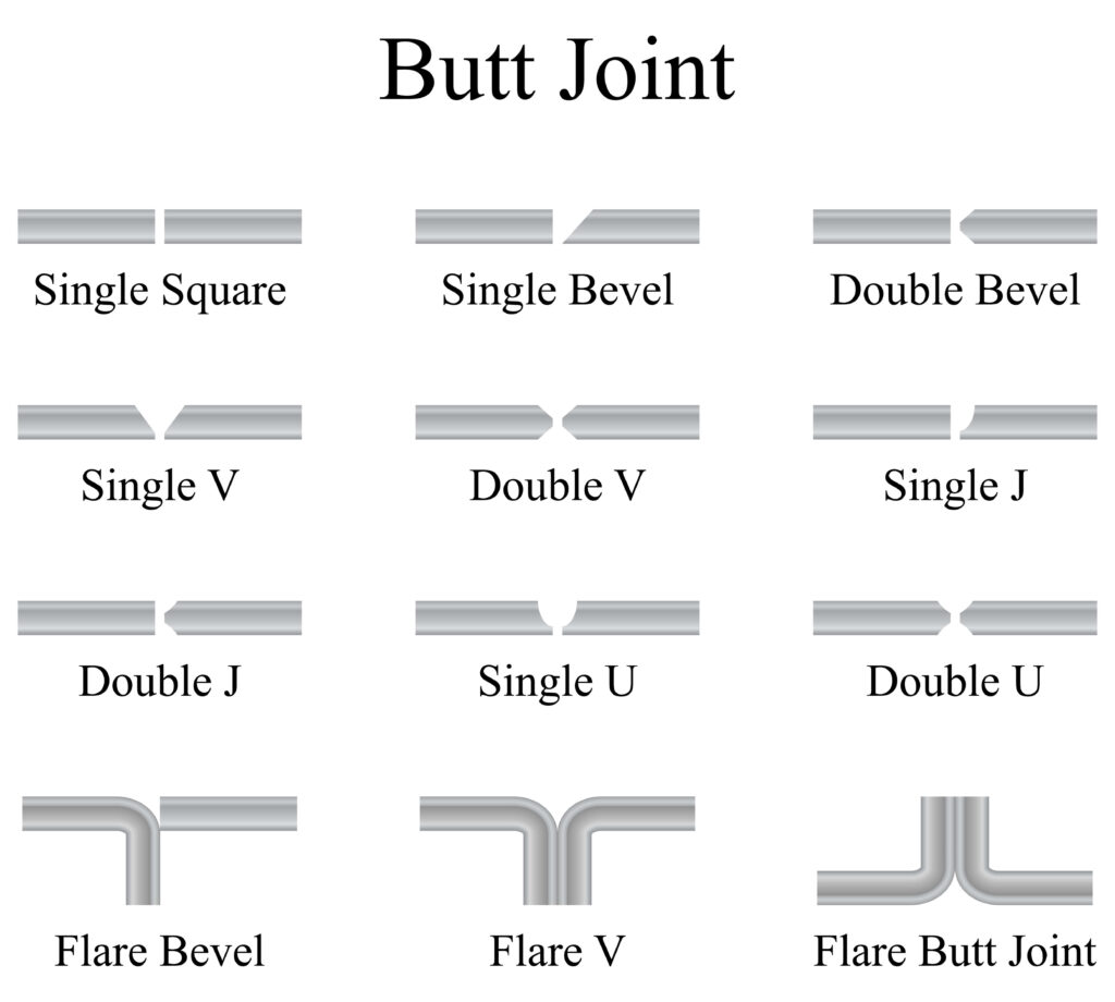
The flare bevel weld melds the metals in curved or tubular metals to either a flat or another curved surface. The weld works very well with piping, pipelines, and various manufacturing processes.
In This Article
What Is a Flare Bevel Weld?
The curvature of one or both pieces of metal causes one or both curved pieces to flare away from the other. The curvature causes a natural bevel or groove that you fill with the weld to join together the two pieces of metal.
With many pieces of metal and welds, you would need to grind an angle on the end of one or both pieces of metal. The bevel creates grooved space that you can fill with the weld.
You can use just about any type of weld to create the flared bevel weld. Arc, MIG, and TIG welding techniques commonly are used. You also could use oxy-acetylene and other types of gas welding to create the weld on thinner pieces of metal.
Two Common Types of Flare Bevel Welds: Groove & V
The flare bevel weld commonly occurs in two types. Those are the flare bevel groove and the flare V groove welds.
What is a Flare Bevel Groove?
The flare bevel groove mostly occurs when you are welding a round, tubular, or curved piece of metal to a flat piece of metal. The curved piece creates the bevel that you will fill with the weld.
What is a Flare V Groove?
The flare V groove creates a natural V shape when joining two curved pieces of metal. If you have two long tubes or pipes touching side by side, a V groove occurs at the top and the bottom.
The metal might be round, like a tube. There also could be two pieces of metal that are flat but have rounded edges that create flared bevels into which you could lay the weld material. Most welders would call that a butt weld, but the principle is the same.
Each of the two types of the weld might occur at the top, at the bottom, or in both locations.
Alternative Names for the Flare Bevel Weld
You may very well know the weld by another name. There are many similar welds that make use of bevels, so they often wind up with alternate references among welders.
The flare bevel weld has commonly used alternative names. They could include:
- Flared groove weld
- Groove weld
- Single flare V-groove weld
- Double flare V-groove weld
- Flared bevel groove weld
Ultimately, they feature the same natural V-shaped groove that is created when joining one or two curved, round, tubular, or flat sections of metal together.
Advantages of the Flared Bevel Weld
The weld produces a naturally occurring V-type of groove that is ideal for accepting a good, strong weld. You do not have to grind or shape either piece of metal, which makes the weld easier, quicker, and safer to perform.
Because you do not have to grind one or both pieces of metal to create the groove, you get to work with thicker pieces. The thickness helps to prevent blowing through the joint or overpenetration with the weld.
The bevel also creates a very inviting space for the weld to occupy and create a strong connection with the other piece of metal. An adequately laid weld that fully occupies the bevel or groove will be just as strong as the rest of the metal and last for an indefinite period when maintained well.
The metal also is less likely to warp or bend due to the heat of your chosen welding method. The rigidity helps to make the weld highly useful in various manufacturing processes.
Potential Disadvantages of the Flared Bevel Weld
Working with thicker pieces of metal can make it harder to get the correct penetration. Ideally, the weld will penetrate all the way through the flat piece without overheating or blowing a hole in it when joining a flat and curved or round piece of metal.
The rounded edge or shape that creates the bevel groove can deflect heat or redirect it toward the other piece of metal. Preheating the area and carefully applying the weld can help to overcome the heat resistance from a round or curved piece of metal.
What the Flare Bevel Weld Symbol Means
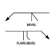
The symbol used to illustrate the type of weld and its location depend on the shape of the metal and where the weld should go. You will use either flat, round, or curved pieces of metal that you join together, and the symbols reflect those shapes.
For example, a straight line represents a flat piece of metal. A semicircle represents a circular or curved piece of metal.
The welding diagram will show where the weld goes along with its size and depth. A good example would be when welding a tube that is 2 inches in diameter to a flat piece of metal.
The weld diagram would show how far the weld should extend from where the pipe is centered against the flat piece.
With a 2-inch pipe, it might say ¾ to indicate three-quarters of an inch from the center. So the crown of the weld should be three-fourths of an inch from the center of the pipe.
The weld symbol also would indicate the depth, such as 3/8. That means the weld should extend for three-eights of an inch into the groove.
How to Measure the Weld
Careful inspection is needed to make sure the weld matches what the design requires as indicated on the diagram. If the flare bevel weld size is smaller than what the diagram shows, the weld is insufficient for the design and might compromise structural integrity.
A skilled and experienced welder can measure the length of the weld along the leg of the flare. The length will determine whether the weld sufficiently extends along the leg as far as the diagram indicates.
The welder also should be an expert in determining the proper depth and penetration of the weld to ensure the flare bevel weld size will provide the structure with the strength needed. An improperly applied weld could compromise the structure of whatever is being built.
Frequently Asked Questions
The size of a flare bevel weld is specified by the dimensions of the leg and root, as well as the included angle of the bevel.
The strength of a flare bevel weld is determined by its cross-sectional area.
A flare bevel weld is typically used to join two pieces of plate together, such as in shipbuilding or in the construction of storage tanks.
Flare bevel weld calculations are typically done using software that can generate 3D models of the weld. The dimensions of the leg and root, as well as the included angle of the bevel, are inputted into the software, which then calculates the size and strength of the weld.
Additional Sources & Resources
Youtube has a lot of great welding resources in general and multiple on flare bevel welds.
There is a great overview of weld joint types:
And this is a good walk through of an effective throat of flare-bevel weld:
Additionally here are more sources you can check out on the topic:
– https://www.ndt-ed.org/EducationResources/CommunityCollege/Welding/weldprocedures/flare_groove.htm
– http://www.wcwelding.com/blog/2017/04/24/what-is-a-flare-bevel-weld/#:~:text=The%20flare%20bevel%20is%20a,of%202%2C5D%2C+or%203D.
– https://kb.esabna.com/kb/assets/03074574enUS.pdf
– https://www.fusionweldingtipsandtricks.com/flare-groove-welding.html
– https://www.lincolnelectric.com/en-us/support/welding-answers/pages/default.aspx?n=4294967552-4294967295-&terms=flare+groove
– https://www.wcwelding.com/blog/2017/04/24/what-is-a-flare-bevel-weld/#:~:text=The%20flare%20bevel%20is%20a,of%202%2C5D%2C+or%203D
– http://www.advancedweldingsolutions.net/files/Flare_Bevel_Welds.pdf
– https://www.ndt-ed.org/EducationResources/CommunityCollege/Welding/weldprocedures/flare_groove.htm
– https://kb.esabna.com/
Image credit: Welding Answers


